HDTV How-To
This page is for you if you are interested in receiving the HDTV Channels that are broadcast over the air free of charge in the Florence area, but are not sure how to do that or if you are having problems receiving the channels.
If you are reading this on paper, you might want to read it online instead at https://westlanetv.org/hdtv-how-to.html so that you can click on the links, see larger versions of the pictures and obtain additional information regarding HDTV and our FM stations. Conversely, if you are reading it online but you want it on paper, you can either try printing this page from your browser or download a pdf of it and print that.
The Basics
To receive WLT’s HDTV broadcasts you need to have a TV that can receive HDTV and a UHF antenna connected to it. All TVs manufactured since March 1, 2007 receive HDTV so the chances are good that you already have a suitable TV. If not, there are many options available locally and on the internet.
We broadcast from a tower that is on the top of Glenada Hill across the Siuslaw River from Old Town Florence. The next time you are enjoying the Port of Siuslaw, look across the river and you will be able to see WLT’s communication towers. If you can see the towers from where your TV is, you can probably get by with connecting a simple UHF indoor antenna to your TV. You will want to point the antenna towards the towers. Under these favorable conditions, most antennas will work equally well. They are easily available to buy locally and on the internet.
If you are further away or have obstacles between your antenna and WLT’s towers, it is more likely that you will need to use a carefully aimed UHF outdoor antenna connected to your TV with a length of cable. UHF outdoor antennas are readily available but vary widely in the range they are designed for. In general, larger antennas will let you overcome longer distances or more obstacles but at some point, the signal will be so weak that it can not be received.
Important Note: Working with outdoor antennas can be hazardous and even deadly. Please, please, please be safe and follow all guidance that your antenna manufacturer provides (an example) and if you have any doubts, please contact a professional.
The Challenge
In the past with analog TVs, you could see how well the signal was received and it was an easy task to move your antenna or make other changes to see if the picture improved or not. With HDTV the transition between no picture and a great picture is much more abrupt. When you are having problems, it can be a challenge to know if the problem is with your cabling, the direction your antenna is pointing or if you need a longer range antenna. When you are receiving HDTV channels, it is difficult to know how well they are being received. If your received signal level is marginal, you may stop receiving channels when conditions change. For example trees reduce signal strength and when their canopies become saturated with rain water your signal is reduced even more.
It is very important that your antenna receives an adequate quality signal. If you are in the lucky situation of having a simple indoor UHF antenna directly connected to your TV then you know that your TV is receiving exactly what your antenna receives. When you have an outdoor UHF antenna and/or have your antenna connected to multiple TVs an additional challenge is added; your signal strength will be reduced the longer your cable is or the more TVs you are connected to.
How is Signal Quality Measured
Signal quality is determined by two measurements: signal level and signal-to-noise ratio. We will use an analogy of listening to music to explain them. The signal level is basically how “loud” the signal is (or the volume of the music). Signal-to-Noise Ratio (SNR) is how well the signal is being received. Think of it as how well you can hear the music over the static. If you are hearing static on the radio station, turning up the volume will not help. For HDTV, antenna amplifiers may be used to increase the signal level to overcome long runs of cables or when the signal is distributed to multiple TVs. However, the SNR can only be improved by improving the antenna you are using. If the signal at your antennas has a poor SNR value, an antenna amplifier will not improve it.
Some TVs may give you some indication of signal quality but it is typically an abstract value of “goodness”. Conceptually, you could use such a TV to check the signal quality for the WLT channels at your antenna and at every location in your house where you have a TV. There are several disadvantages though:
- TVs do not typically give you measurements for both level and SNR,
- TVs do not show signal quality for all the channels at once, and
- connecting a TV directly to your outdoor UHF antenna could be difficult.
Measuring Signal Quality with a Signal Meter
To help people overcome this challenge, West Lane Translator has donated a kit containing a Psiber SignalScout 40 (SS40) along with a GE Pro Bar HD Antenna to the Siuslaw Public Library.
The meter provides a way to show the quality of the received signal for the channels we broadcast all at the same time. In addition, it is highly portable because it is small and is powered by an internal rechargeable battery.
The Signal Meter Kit
This is what the kit looks like:
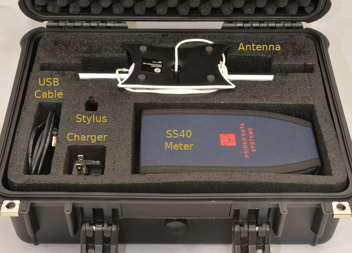
The kit consists of:
- the SS40 meter in its protective nylon cover,
- a charger for the SS40 with USB output,
- a USB cable to connect the charger to the SS40,
- a stylus for use on the SS40’s touchscreen,
- the GE Pro Bar HD UHF indoor antenna with an attached 66” long cable,
- a hard case with compartments for all the other pieces, and
- a printout of this guide (not shown in the picture above).
Please ensure that all components are in the case before returning the meter.
The included UHF indoor antenna can be used with the meter or your TV to get an idea of how well a simple indoor antenna will receive WLT’s HDTV channels in your location.
Using the Meter
These instructions will try to make the meter easy to use by walking you through step by step. The images can be clicked on to make them larger.
Charging the Meter
It is a good idea to charge the meter’s battery when you get it home. The meter should also be charged before returning it.
| Remove the meter, charger and USB cable from the hard case. If the case is hard to open even after unlatching it, the knob under the handle can be turned counter-clockwise to equalize the pressure in the case and then back clockwise to seal the case again. | 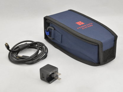 |
| Open the meter’s nylon protective cover. | 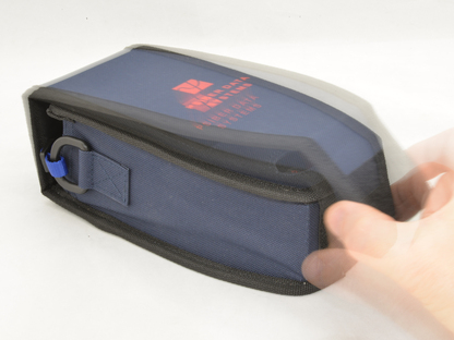 |
| Flip the nylon protective cover behind the meter and reattach it like an easel. | 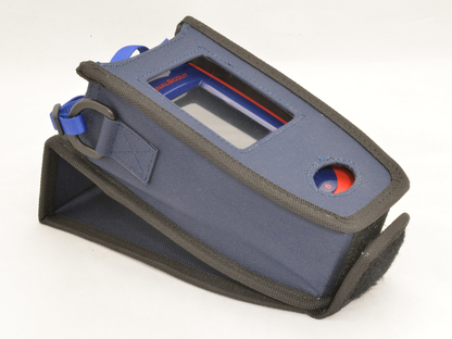 |
| Flip open the plastic lid on the top of the meter. | 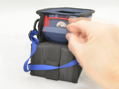 |
| Connect the small end of the charging cable to the meter. | 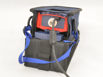 |
| You may need to unfold the prongs on the charger that plug into the AC outlet. | 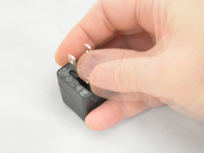 |
| Connect the large end of the charging cable to the charger. | 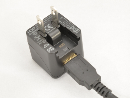 |
| Plug the charger into an AC outlet. You can continue on to the next section “Getting Started with the Meter” while the meter charges. | 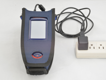 |
Getting Started with the Meter
The following steps will familiarize you with the operation of the meter and ensure that it is configured correctly. If you do modify the configuration away from what is documented here, please undo your changes before you return the meter.
| Connect the antenna’s cable to the threaded connector under the plastic lid on the top of the meter by turning the outer part of the antenna’s connector clockwise. The connectors can be fussy but careful alignment of the connectors will help. Finger tighten the connector. If you are using the antenna that is part of the kit, orient it so that either flat side points toward the antenna towers on Glenada Hill. | 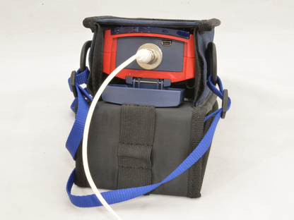 |
| Turn on the meter by pressing and holding the power button for a second until the screen turns on. The meter is turned off in the same way. HINT: The power button can be pressed twice quickly as a shortcut to return to the home screen at any time. | 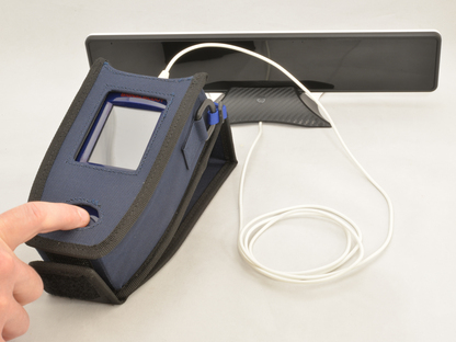 |
| After the meter is powered on, its home screen is displayed. The icon at the top right corner of the screen indicates how full the battery is. When the battery is fully charged, all the segments of the battery icon will be green. When the battery is being charged, the red tip on the very right of the icon will be on. The screen is a touch screen which works best when it is touched with the stylus included in the kit. If the large vertical button on the left side of the screen shows CATV, press it with the stylus to change it to say ATSC. The image at right shows the meter in the correct ATSC mode. | 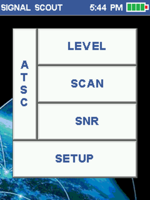 |
| Press the SETUP button on the screen with the stylus to enter the setup menu shown. | 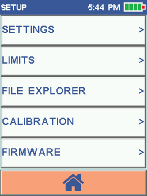 |
| Press the FILE EXPLORER button on the screen with the stylus so prior customizations can be removed. USER SETTINGS should be highlighted as shown, but if it is not, press it with the stylus. Delete the prior user’s settings by pressing the image of the trash can in the bottom right corner with the stylus. A confirmation will appear on the screen; press YES to confirm the deletion. Press METER CAL (User) at the bottom of the screen to highlight it and once again press the trash can and then confirm by pressing YES to delete the prior user’s meter cal also. When done, press the circular arrow at the bottom left corner of the screen to return to the setup menu. | 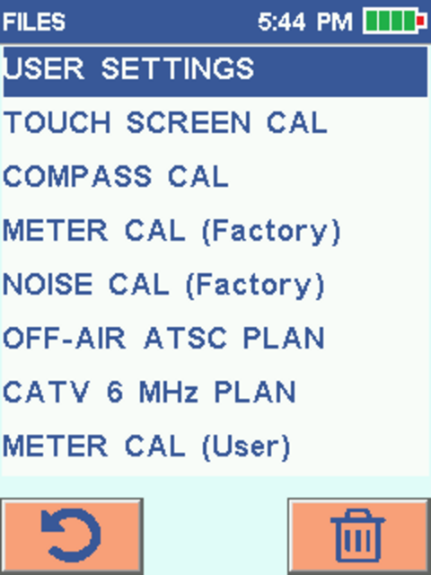 |
| Press the SETTINGS button on the screen with the stylus to enter the settings screen as shown. If the time or date are incorrect, you may optionally correct them by touching the value with the stylus and then entering the correct value (note that the time is entered in 24 hour format so add 12 to the time if it is afternoon). The recommended values for the other settings are shown in the image to the right. They can be changed by pressing the empty square that you want checked. The Speaker Level can be changed to enable a clicking sound when the screen is touched. The minimum Auto Off value of 5 minutes is recommended to extend battery life, but can be changed if needed. Automatic Gain Control needs to be changed from On to Off. If it is not off, you may be confused by the readings because the meter can automatically offset the values displayed. When done, quickly press the power button twice to return to the home screen. | 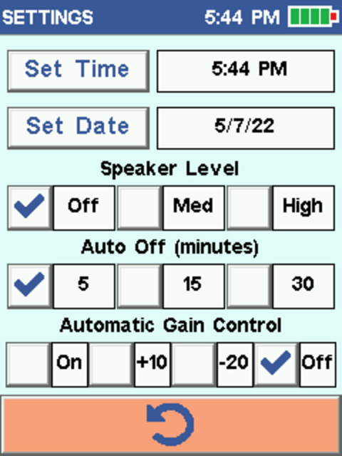 |
Signal Quality Measurements
This section will provide you with background information that you will need to effectively use the meter. While you read this section, you can set the meter aside and let it continue to charge, which it will do even when its display is off.
As mentioned in a note on the HDTV Channels page, subchannels are available for each HDTV channel. The main channel and subchannels are all part of the same digital transmission so the level and SNR will be identical for all of them. The meter displays information about channels without the decimal suffixes because of this.
The meter displays the signal level in dBm. A good signal level is typically between -35 dBm and -70 dBm. Note that these values are negative and higher values are better so -35 dBm is better than -70 dBm. The other important thing to know is that dBm measurements are logarithmic. That means that small changes in dBm values can indicate a large change in the signal level. A 3 dBm improvement (e.g. from -60 dBm to -57 dBm) means the signal level has been improved twofold. A 10 dBm improvement (e.g. from -60 dBm to -50 dBm) means the signal level has been improved tenfold.
SNR is measured in dB. SNR values over 25 dB are ideal and values under 20 dB mean the signal is practically unusable. The values are positive but dB units are also logarithmic so once again, 23 dB is two times better than 20 dB and 30 dB is 10 times better than 20 dB.
If you would like more information, this blog post by the retailer Solid Signal was the basis for this section and is a good introduction.
To summarize, the SNR needs to be at least 20 dB and preferably over 25 dB at your antenna and in addition, the signal levels need to be between -35 dBm and -70 dBm. If the SNR or signal level is low, you can try changing:
- where your antenna is pointing,
- where your antenna is mounted (in general higher is better), or
- what antenna you are using.
Once the signal at your antenna is adequate, you should also check the SNR and signal level at each TV (assuming your antenna is not connected directly to the TV). If there isn’t adequate signal level at your TVs, an antenna amplifier may be used to boost the signal level.
Signal Measurement Screens
The meter has three different measurement screens that are selected by using the stylus to press LEVEL, SCAN or SNR on the home screen. You can return to the home screen from these screens by either tapping the power button twice or using the stylus to press the lower-left button on the screen that looks like a house.
The LEVEL screen shows detailed information about a single channel at a time. The SCAN screen shows the signal level for all the channels at once, while the SNR screen shows the SNR for all the channels at once. As mentioned above, the SNR is critical for reception so we will start with that screen.
The meter displays the signal level on all three of the signal measurements screens. If the meter is displaying signal levels as dBmv instead of the dBm units this document uses, just press the stylus on the word dBmv on the screen and the meter will flip back to showing dBm.
| SNR Screen The majority of the SNR screen displays a bar graph that shows the SNR for all five of WLT’s channels. The two lines of numbers under the bar graph are the channel numbers. The top line of these show the Florence Channels as listed on our HDTV Channels page. The bottom line shows the Eugene Channels which you are probably more familiar with. If the channels you see do not match the image shown to the right, you will need to follow the instructions in the next section “Resetting the Meter to Show WLT Channels” to reset them. The LEVEL and SNR boxes at the bottom of the screen show the numerical signal level and SNR for the blue highlighted channel. The highlighted channel can be changed by pressing the circled arrow buttons at the bottom of the screen with the stylus. The meter incorporates a compass. The “NW” towards the top left corner of the screen shown to the right indicates the meter was pointed roughly northwest. The compass works best when the meter is lying flat on its back and it indicates the direction that the antenna connector is pointed. Notice that the SNR of channel 35 (9) on the far right is marginal (between 20 and 25 dB as mentioned above). The other four channels all have good SNR values. |
 |
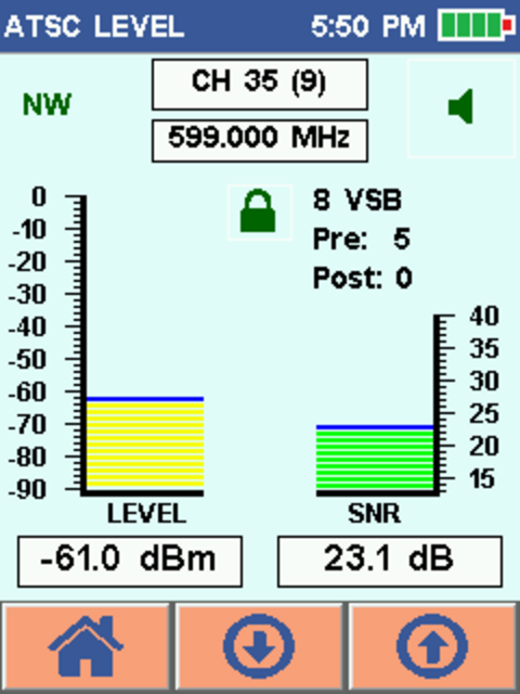
| To find out what the actual SNR value of channel 35 (9) is, press the circled arrow pointing down at the bottom of the screen. Alternatively you could press the circled arrow pointing up four times. The selected channel will change to be 35 (9) and the signal level and SNR will be displayed for it. In the screen shown to the right, note that the SNR is marginal at 23.4 dB. You can try to improve it by repositioning the antenna as you monitor the meter. Even if it can not be improved, you will probably be satisfied with your reception of channel 35 (9) at the time but you may lose reception of it under worse conditions. Changing your antenna to one rated for a longer range should improve the SNR. | 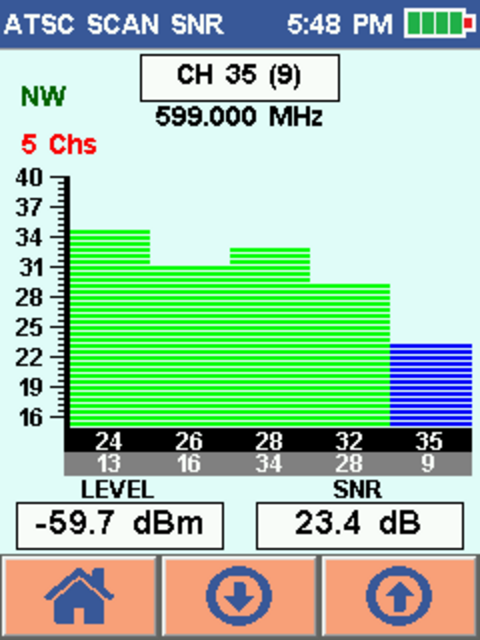 |
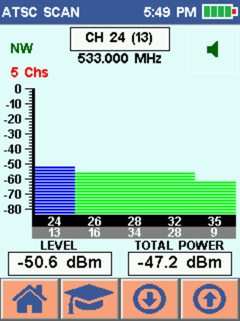
| SCAN Screen The scan screen is very similar to the SNR screen except that it displays the signal level instead of the SNR. As mentioned above, the signal level needs to be between -35 dBm and -70 dBm. As an example, all of the signal levels on the screen shown to the right are fine. The scan screen has two features that are not on the SNR screen. The first is the speaker icon in the upper right corner of the display. It can be pressed with the stylus to enable or disable an audible tone that is proportional to the signal strength. The other feature is the extra button at the bottom of the screen that looks like a mortarboard hat. That button scans for the channels that can be received but it probably will not be useful because the meter has already been preset with WLT’s channels. If you press it and want to restore the channels back to normal, just go to the home screen and then back to the scan screen. |
 |
| LEVEL Screen The level screen shows more information about a single channel at a time which can be changed by pressing the circled arrow buttons at the bottom of the screen with the stylus. The signal level and SNR are displayed both as a bar graph and numerically. Similar to the scan screen, the speaker icon in the upper right corner of the screen can be pressed with the stylus to enable or disable an audible tone that is proportional to the signal strength. The padlock towards the center of the screen will be green and locked when the channel is being successfully received. If the padlock is red and unlocked, the channel can not be received. When the channel is being received, three lines of text will be displayed to the right of it. The first line will always be “8 VSB” which is how the channel is encoded. The next two lines are very useful. “Pre” indicates the number of errors in the received digital transmission that can be corrected by a TV’s error correction. “Post” indicates the number of errors that can not be corrected and will cause visible problems in the received channel. In the image shown to the right channel 9 is selected (as shown in the parenthesis at the top of the screen). As noted in the SNR Screen section above, the SNR for channel 9 is marginal so it is not surprising that some errors are being encountered. In this case, all the errors are correctable but if conditions were to worsen, the errors may become uncorrectable. |
 |
Resetting the Meter to Show WLT Channels
These steps only need to be done if you don’t see the five WLT channels as shown above in the images of the SNR and SCAN screens. If the channels are displayed properly, you can skip this section and go on to the “Final Notes” section.
| As you did in the Getting Started, press the SETUP button on the home screen and then the FILE EXPLORER button on the setup screen to get to the FILES screen. Press Off-Air ATSC PLAN with the stylus to select it. The meter will add a new button that looks like a pencil writing on paper in the center at the bottom of the screen. This button lets you edit the ATSC plan (the channels that will be displayed). Press the edit button with the stylus. | 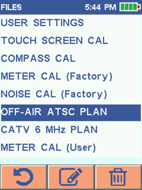 |
| The prior step brings up a screen similar to the one shown at right. Look at the second button from the left at the bottom of the screen. If it is a check mark, press it. That will check all the channels’ “Use” boxes so they will be displayed on the measurement screens. It will also change the check mark button to be a filled-in square as shown at the right. When you see the filled-in square button, press it and that will uncheck all the “Use” boxes so that no channels will be displayed on the measurement screens. This will be a good starting point to enable WLT’s five channels. | 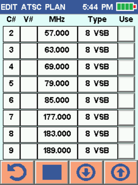 |
| Press the circular down arrow button at the bottom of the screen twice to get to the page of channels that has channel 24 in the C# (channel number) column. Press the empty box to right of the 24 that is in the V# column. Press “1”, “3” and then the blue enter arrow. Next press the empty box at the end of the 24 row in the “Use” column so that there is a check mark. The meter screen should look like the image to the right. Press the circular down arrow button at the bottom of the screen once to get to the page of channels that has channels 26, 28 and 32 in the C# column. | 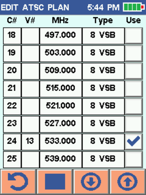 |
| In the same manner as in the prior step, set V# to 16 for C# 26, V# 34 for C# 28 and V# 28 for C# 32. Also turn on the check mark for C# 26, 28 and 32. The screen should look like the image to the right. Press the circular down arrow button at the bottom of the screen once to get to the page of channels that has channel 35 in the C# column. | 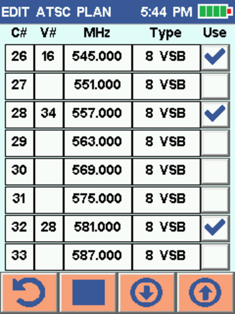 |
| On this screen, set V# to 9 for C# 35 and turn on the check mark for C# 35 and verify against the image shown to the right. Press the circular arrow at the bottom left corner of the screen and then press “YES” when asked if the Channel Plan should be saved. The meter has now been set to show just the Florence WLT channels with their equivalent Eugene channels. Quickly press the power button twice to return to the home screen. | 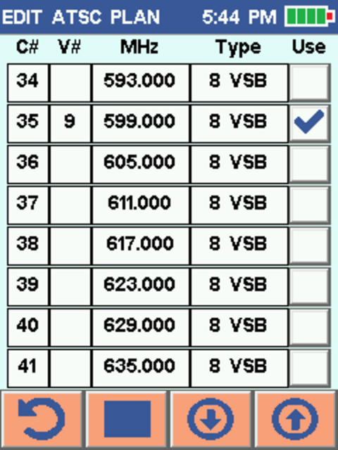 |
Final Notes
You are now ready to start using the meter to diagnose your HDTV reception. When you are ready to return the meter, please ensure that all settings have been restored as previously described, the battery has been charged and everything has been put back in the case.
If you have any problems with or questions about using the SS40 for checking for reception of WLT’s channels, please contact us and specify “Problems with the Library’s Signal Meter” in the “Category” of the form.
Many thanks to Psiber Data Systems Inc. for making the SignalScout 40 (SS40) as well as for their help in producing and permission to use the screen images on this page. More information about the SignalScout 40 including videos and manuals is available on its product page.
Quick Reference
-
The SNR needs to be at least 20 dB and preferably over 25 dB.
-
The signal levels need to be between -35 dBm and -70 dBm.
| Signal Meter Channel |
Eugene Channel |
Program Content |
|---|---|---|
| 24 | 13 | CBS/TBD/Charge! |
| 26 | 16 | NBC/CW/Comet |
| 28 | 34 | Fox/My TV |
| 32 | 28 | OBP |
| 35 | 9 | ABC/MeTV/ION/H&I/Start |